216 BEGINNING OF THE MINICOMPUTER
<0:11 >), an accumulator extension bit called the Link (L\Link), the 12-bit Program Counter, the RUN flip-flop, and the INTERRUPT.ENABLE bit. The external processor state is composed of console switches and an interrupt request.
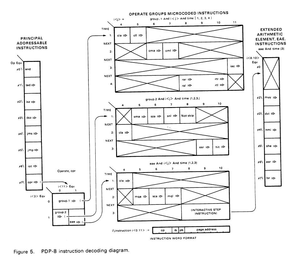
The instruction format can also be presented as a decoding diagram or tree (Figure 5). Here, each block represents an encoding of bits in the instruction word. A decoding diagram allows one more descriptive dimension than the conventional, linear ISPS description, revealing the assignment of bits to the instruction. Figure 5 still requires ISPS descriptions for the memory, the processor state, the effective address calculation, the instruction interpreter, and the execution for each instruction. Diagrams such as Figure 5 are useful in the ISP design to determine which instruction operation codes are to be assigned to names and operations, and which instructions are free to be assigned (or encoded).