Start signal to activate the first control module. When the AUTO/MANUAL switch is set to AUTO, the RTM system is in continuous operation (i.e., running). When the switch is set to MANUAL, then pulsing (depressing) the SINGLE STEP switch will cause one Bus transfer at a time to be executed (the SINGLE STEP switch does this by
withholding the Bus DONE signal until it is pulsed).
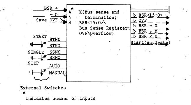
3.It provides the reset signal, called POWER CLEAR, which initializes all modules when power is turned on. A switch can also be connected to provide this function manually.
4.It allows sense lights to be connected to the BSR register so that data transfers that use the Bus may be monitored.
5.It provides for a word source of zero, through the operation <-0.
6.It allows the transfer of data to the BSR for testing, through the operation BSR<-.
7.It forms the following Boolean outputs which are available after each
control step using the Bus:
BSR<15:0> = 0 (detects whether the last word transferred was a zero)
BSR<15:0> > 0 (detects whether the last word transferred was positive)
BSR<15.0> ( 0 (detects whether the last word transferred was negative)
BSR<15:0> (16 Booleans, one for each bit)
OVERFLOW\OVF (the carry out from an addition, borrow out from a subtraction, or the shift out from a shift)
Fig. 14. Module diagram of K(bus sense and termination) module
Whenever the OVF signal on the Bus is to be saved in the OVF bit register, the Save OVF input to Kbus must be evoked. This operation does not cause a redundant DATA ACCEPTED\DA timing signal to be produced (see discussion of
46