174 Part 2 The instruction-set processor: main-line computers
Section 2 Processors with a general register state
current in the meantime continuing to flow through the diodes with little loss in the stored energy of L, since the voltage across L is low at this time.
The output cathode-follower V2 is caught at -10 volts in the negative direction by a diode; this safeguards the crystal-diode circuits driven by it in the event of failure of the h.t. supply or V2, audit removes residual ripple on the bottom of the input waveform, and thus reduces the back voltage and hence leakage in diodes of gates driven by the output.
The second output through a diode can be used in conjunction with similar outputs from other circuits and a resistor (pins 3 and 4) to make an 'or' (up to about 16-way).
In general, each output circuit has two available load resistors, disposed between direct and 'or' outputs according to a set of rules which are applied for each case. The number of units which can be driven by an output can vary between three and 16 according to circumstances; where more have to be driven than the rules allow, use is made of 'booster' cathode-followers available on one of the packages.
Some examples of the use of the logical circuits
Two examples will be given, the first being a simple arrangement-the staticizor-which is used frequently, and the second being a complicated arrangement-the adder/subtracter-which is used infrequently. The symbols used to indicate the circuit units are shown in Figs. 2c and 5b.
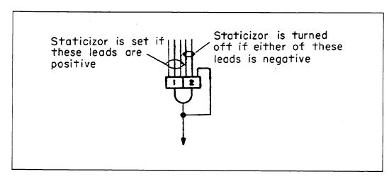
The staticizor. The function of a staticizor is to remember the fact that a digit occurred at a particular time, for an indefinite period, the method generally used in Pegasus being shown in Fig. 4. A digit delay with a twin 'and' gate input has its output connected to one of its inputs. It is turned on by gate 1, which causes a digit to circulate as long as the inputs to gate 2 remain positive.
Fig. 4. The staticizor.
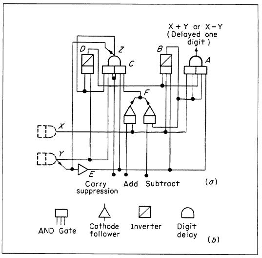
Fig. 5. The adder/subtracter.
It is normally turned off by an inverted pulse (a '0' following a series of l's) on one of the gate 2 inputs.
The adder/subtracter. Figure 5 shows an adder/subtracter unit with inputs X and Y and an output X + Y for the sum or X - Y for the difference. There are two further input control leads marked 'add' and 'subtract'. If the 'add' lead is held positive while the 'subtract' lead is held negative, the unit acts as an adder. If the 'subtract' lead is held positive and the 'add' lead negative, the unit acts as a subtracter. Carry suppression is controlled by the lead marked 'carry suppression'. Carries are allowed to propagate when this lead is held positive, so that a negative signal on this lead will suppress carry.
Table 1 gives the digits appearing at the outputs of logical elements in the adder/subtracter unit for all combinations of input and carry digits when the unit is operating as an adder.
Arrangement of circuits based on packages
It was required to base the logical circuits on a standard size of package which could also be used for other circuits, e.g. a nickel-line 1-word store [Fairclough, 1956]. A unit which could accommodate three valves and had a 32-way plug was decided on; the