Chapter 9 The design philosophy of Pegasus, a quantity-production computer 173
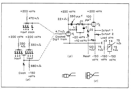
Fig. 2. Digit-delay circuit.
in cascade in Pegasus is five, though up to 12 could be performed in special circumstances.
The logical circuits. Each of the logical packages has more than one circuit unit. A circuit unit is defined as that part of a package which has input and output pins, and no connections to other parts of the package other than supplies. We may make the following generalizations:
a Each unit has an 'and' gate at its input.
b Each unit has a cathode-follower output (half a 12AT7 valve).
c Each unit has an additional output via a germanium diode for making 'or' gate connections.
[Note: There are exceptions to (a) and (c) on one package type.]
There are three possibilities for the part of the circuit unit between the input 'and' gate and the output cathode-follower, namely a digit delay (half a 12AT7 valve), an inverter (half a 12AT7 valve), and a direct connection. Space does not permit a description of all the circuits, so it is proposed to deal only with the digit delay.
The circuit is shown in Fig. 2, and some typical waveforms are shown in Fig. 3. The input circuit can be of two forms, namely a 3-input 'and' gate and two such gates with their outputs 'or-ed' together. In both cases there is a further gating with a clock pulse. The clocked digits from the gate input circuit are applied to the grid of V1, the anode voltage of which falls, so building up a current in L. When V1 is cut off at the end of the digit, this current flows through diodes D1 and charges up a storage condenser, C, which is discharged at the end of the next clock pulse by a 'reset' pulse applied through D2. The reset pulse supply is a common computer supply whose amplitude and phasing relative to the clock pulse is shown in Fig. 3.
It will be noted that the reset pulse is also present at a time, just after V1 is cut off, when the current in the inductor is about to charge the storage condenser. This merely has the effect of deferring the charging of C until the end of the reset pulse, the
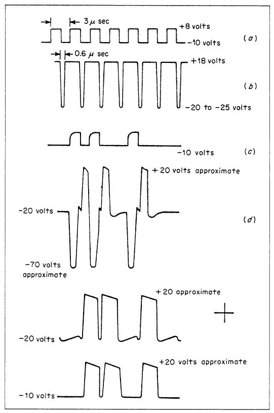
Fig. 3. Digit-delay waveforms.