Chapter 18 ½ The IBM System/360 Model 91: Machine Philosophy and Instruction-Handling 277
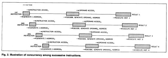
possible to enter instructions into the hardware sets at shortly spaced time intervals. Then, following the delay caused by the initial filling of the line, the execution results will begin emerging at a rate of one for each time interval. Figure 2 illustrates the objective of the technique.
Defining the time interval (basic CPU clock rate) around which the hardware sets will be designed requires the resolution of a number of conflicting requirements. At first glance it might appear that the shorter the time interval (i.e., the time allocated to successive assembly line stations), the faster the execution rate will be for a series of instructions. Upon investigation, however, several parameters become apparent which frustrate this seemingly simple pattern for high performance design. The parameters of most importance are:
2 The amount of control hardware-and control complexity-required to handle architectural and machine organization interlocks increases enormously as the number of assembly line stations is increased. This can lead to a situation for which the control paths determining the gating between stations contain more circuit levels than the data paths being controlled.
2 Effective storage access time, especially when this time is relatively short. Unless the station-to-station time interval of the CPU is a sub-multiple of storage access time the synchronization of storage and CPU functions will involve overhead time.
It can be seen in Fig. 3 that the basic time interval accommodates the assembly line handling of most of the basic hardware functions. However, the storage and many execution operations
1The design objective calls for a 60 nsec basic machine clock interval. The judgment exercised in this selection was tempered by a careful analysis of the number of circuit levels, fan in, fan out, and wiring lengths required to perform some of the basic data path and control functions. The analysis indicated that 11 or 12 circuit levels of 5-6 nsec delay per level were required for the worst-case situations.
2Figure 3 also illustrates that the hardware sets are grouped into larger units-instruction unit, main storage control element, fixed-point execution unit, floating-point execution unit. The grouping is primarily caused by packaging restrictions, but a secondary objective is to provide separately designable entities having minimum interfacing. The total hardware required to implement the required CPU functions demands three physical frames, each having dimensions 66" L ´15" D ´78" H. The units are allocated to the frames in such a way as to minimize the effects of interframe transmission delays.