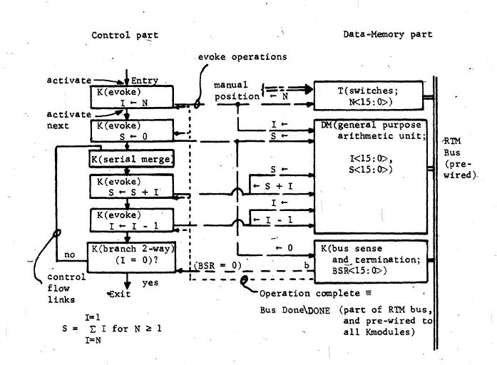
Fig. 6. RTM diagram for summing positive integers from 1 to N.
the data-memory part of the system. The remaining modules, the control part of the system, specify the algorithm by causing operations to be performed on the data, and causing data to be transferred in the data-memory part.
The descriptions that are given in this section of the chapter are at the RT level of detail. The user, whether he is interested in using RTM's as a design notation or actually wants to build an RTM system, need only understand this level. Those who wish to understand the switching circuit level of the modules should consult Chapter 7.
33