Chapter 14
Instruction logic of the MIDAC1
John W Carr III
The MIDAC, Michigan Digital Automatic Computer [Carr, 1956], was constructed on the basis of the design of the SEAC at the National Bureau of Standards. Its instruction code is particularly of interest because it incorporates the index register concept into a three-address binary instruction. Numbers in this machine are (44, 0, 0)2 fixed points. The word length is 45 binary digits with serial operation.
Word structure
The data or address positions of an instruction are labeled the a , b , and g positions. Each contains twelve binary digits represented externally as three hexadecimal digits. Four binary digits, or one hexadecimal digit, are used to convey the instruction modification or relative addressing information. The next four binary digits or single hexadecimal digit represents the operation portion of the instruction. The final binary digit is the halt or breakpoint indicator for use with the instruction.
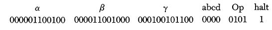
For example, the 45-binary-digit word
000001100100000011001000000100101100000001011
considered as an instruction would be interpreted as
In external hexadecimal form this would be written
064 0c8 12c 0 5 -
The above binary word is the equivalent machine representation of the following instruction: "Take the contents of hexadecimal address 064, add to it the contents of hexadecimal address 0c8, and store the result in hexadecimal address 12c. There is no modification of the 12-binary-digit address locations given by the instruction. Upon completion of the operation, stop the machine if the proper external switches are energized." The binary combination represented by 5 is the operation code for addition.
Data or addresses
The addresses given by the twelve binary digits in each of the three locations designate in the machine the individual acoustic storage cells and blocks of eight magnetic drum storage cells. The addresses from 0 to 1023 (decimal) or 000 to 3FF (hexadecimal) correspond to acoustic storage cells. The addresses from 1024 to 4095 (decimal) or 400 to FFF (hexadecimal) correspond to magnetic drum storage blocks. In certain operations, however, the addresses 0 to 15 (decimal) or 0 to F (hexadecimal) represent input-output stations rather than storage locations.
These twelve-binary-digit groups will in some cases be modified by the machine in order to yield a final twelve-binary-digit address. The method of processing will depend on the values of the instruction modification digits. After modification, the final result will then be interpreted by the control unit as a machine address.
In some instructions, namely those that perform change of control operations, which involve cycling and counting rather than simple arithmetic operations on numbers, the a and b positions in an instruction are not considered as addresses. In those cases, they are used instead as counters or tallies. In other instructions, which do not require three addresses, but only one or two, the b position is not considered as an address. In these cases, the oddness or evenness of the b address is used to differentiate between two operations having the same operation code digits. That is, the parity of binary digit P22 is used as an extra function designator.
Instruction modification digits
The four binary digits P9-P6 are used as instruction modification or relative addressing digits. Their normal function is relatively simple; nevertheless, the possible exceptions to the general rule can make their behavior complicated. These four digits are labeled
1
In E. M. Crabbe, S. Ramo, and D. E. Wooldridge (eds.), "Handbook of Automation, Computation, and Control," vol. 2, chap. 2, pp. 115-121, John Wiley & Sons, Inc., New York, 1959.209