Chapter 10 An 8-bit-character computer 185
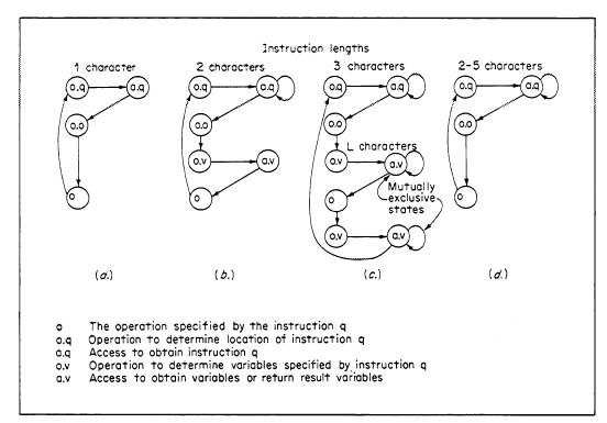
Fig. 2. An 8-bit-character-computer instruction-interpretation state diagram. (a) No parameters; (b) integer or relative address; (c) direct address; (d) immediate data.
The general registers discussed above are similar to those of the general register processors. Since it is assumed that this type of processor might be used to interpret another ISP, the +1 and -1 instructions provide for both string and stack memory operations. The instructions for a microprogrammed P and the I/O devices are not defined. For example, a 16-way branch instruction which branched to one of 16 locations based on 4 bits of the accumulator might facilitate writing an interpreter.
The ISP is given in Appendix 1 of this chapter. The Pc state is organized about a small scratch-pad memory, although Mp could be used instead. The instruction formats and the operation code assignments are shown in Fig. 1.
The instructions behave as illustrated in the state diagram (Fig. 2). For example, the instruction "lri 3, A90716" is coded
and the effect is
R[3] á 0 : 15ñ ¬ A90716
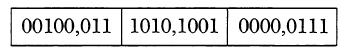
The instruction, xor 3, with L = 2, is coded
![]()
and the effect is
R[0] á 0 : 23ñ ¬ R[0] á 0 :23ñ Å R[3] á 0:23ñ
In these examples, the behavior of lri and xor is specified in the state diagrams of Fig. 1d and 1a, respectively.
An open subprogram to perform the n-component vector (16-bit) addition1 ¬
A ¬
¬
B + ¬
C is
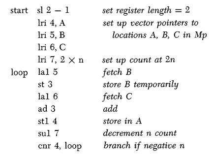
The above program loop is nine characters long. A program loop for the IBM System/360 is about 16 characters long. The setup is 13 characters, as opposed to 6 ~ 16 characters for the 360.
Conclusions
We have violated our principle of showing "real" computers by designing this computer. We think it is typical of a small processor, but slightly more interesting.
1The length is specified by register L.