18 Part 1½ Fundamentals Section 1 ½Abstraction and Notation
Processor, P. A component that is capable of interpreting a program
in order to execute a sequence of operations. It consists of a set of operations
of the types already mentioned-M, L, K, S, T, and D-plus the control necessary
to obtain instructions from a memory and interpret them as operations to
he carried out.
Computer Model (in PMS)
Components of the seven types can be connected to make stored-program digital computers, abbreviated by C. For instance, the classical configuration for a computer is
![]()
Here Pc indicates a central processor and Mp a primary memory, namely, one which is directly accessible from a P and holds the program for it. T is a transducer connected to the external environment, represented by X. (The colon-equals (: =) indicates that C is the name of what follows to the right.) Thus a computer is a central processor connected to its primary memory on the one hand and to a transducer on the other, which is what an input/output device is.
Actually the classic diagram had four components, since it decomposed the Pc into a control (K) and an arithmetic unit or data-operation (D):
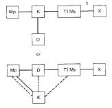
where the solid information-carrying lines are for instructions and
their data and the dotted lines signify control.
Often logic operations were lumped with control, instead of with data
operations, but this no longer seems to be the appropriate way to decompose
the system functionally.
If we associate local control of each component with the appropriate component, we get
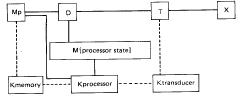
where the solid lines carry the information in which we are interested and the dotted lines carry information about when to evoke operations on the respective components. The solid information-carrying lines between K and Mp are instructions. Now, suppressing the K's, then lumping the processor state memory, the data operators, and the control of the data- operations to form a central processor, we again get
![]()
Computer systems can be described in PMS at varying levels of detail. For instance, in the diagrams above we did not write in the links (L's) as separate components. These would be of interest only if the delays in transmission were significant to the discussion at hand or if the i-units transmitted by the L were different from those available at its terminals. Since this is not usually the case in current computers, one indicates simply that two components (e.g.; an Mp and a Pc) are connected together. Similarly, often the encoding of information into i-units is unimportant; then there is no reason to show the T's. The same statement holds for K's. Sometimes one wants to show the locus of control, say when there is one control for many components, as in a tape controller, but often this is not of interest. Then there is no reason to show K's in a PMS diagram.
As a somewhat different case, D's never occur in PMS diagrams of computers, since in the present design technology D's occur only as subcomponents of P's. If we were to make PMS-type diagrams of analog computers, D's would show extensively as multipliers, summers, integrators, etc. There would be few memories and variable switches. The rather large patchboard would be represented as a very elaborate, manually fixed switch.
Components are often decomposable into arrangements of other components. Thus, most memories are composed of a
1The vertical bar expresses mutually exclusive alternatives.
Here, a T or Ms exists at the periphery.