ISPS PRIMER FOR THE INSTRUCTION SET PROCESSOR NOTATION 521
constitutes an extended accumulator LAC. The structure of the extended accumulator is shown below:
The expression < > indicates a single, unnamed bit (L is only one bit long and there is no need to specify a name for it,)
The Program Counter (PC) is used to store the address of the current instruction being executed as the machine steps through a program:
PC\Program.Counter<0:1 1>,
Twelve bits are needed in the PC to address all 4,096 locations of primary memory.
In the PDP-8, I/O devices are allowed to interrupt the central processor. When a device requires service from the central processor, it emulates a subroutine call, forcing the processor to execute an appropriate I/O subroutine. The presence of an interrupt request is indicated by setting the INTERRUPT.REQUEST flag. The processor can honor these requests or not, depending on the setting of the INTERRUPT.ENABLE bit:
INTERRUPT.ENABLE<>,
INTERRUPT.REQUEST<>,
There are 12 console switches which can be read by the processor. These switches are treated as a 12-bit register by the central processor:
SWITCHES<0: 11>,
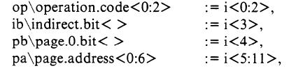
Instruction Format
As is the case with most data-types and registers on the PDP-8, instructions are 12 bits long:
i\instruction <0:11>,
An instruction is a special kind of data-type. It is really an aggregate of smaller information units (operation codes, address modes, operand addresses, etc.). The structure of the instructions must be exposed by describing the format. Most PDP-8 instructions contain an operation code and an operand address: