162 BEGINNING OF THE MINICOMPUTER
790 machines had been shipped - more than the total of all other DEC 18-bit machines.
Two of the PDP-l5 models are of special interest. A dual central processor version and the PDP- 15/76. These are treated separately below.
DUAL CENTRAL PROCESSOR PDP-15
In 1973 the PDP-15 product line proposed and sold a system that was a dual processor. From the dual processor project came a dual port memory, which eventually was transferred to the PDP-15 standard product line. The dual port memory also expanded memory to the full 128 Kwords built into the PDP-15 addressing structure. The unit occupied a single rack and used the M-Series logic modules. Because there was space to add a third port within the rack unit, the dual port memory was actually built to be a three port device. At the time, the laboratory breadboard was an impressive array of three cabinets containing 128 Kwords of memory and two processors.
The logic included what went unrecognized as a "synchronizer" problem for two months, despite reviews by some senior engineers. The synchronizer problem, first described by Chaney and Molnar [1973] of Washington University, is a classical logic design problem that is theoretically unsolvable. When synchronizing (detecting) the presence of an event occurring at a random time relative to a fixed clock event, a small amount of energy is available to set the flip-flop. When the flip-flop is triggered with such a small signal, it can go into an undecided (metastable) state for a relatively long (even indeterminant) period of time. The problem occurred in the dual port memory design because the three inputs (2 ports and the memory clock) needed to be synchronized. Despite the theoretical lack of a solution, the practical solution is usually to wait longer (e.g., two clock times) or to improve the circuit by unbalancing it. Once the problem was recognized, the design went to a quick completion.
PDP-15/76
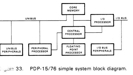
Of the systems listed in Table 2, the PDP-15/76 was one of the most interesting. A simplified block diagram of the final evolved state of the PDP-15/76 is shown in Figure 33. The diagram is referred to as an evolved design because the PDP-l 1 connection and the floating- point arithmetic features were not part of the original PDP-15 design.
The design of the PDP-15/76, also referred to as the Unichannel 15/76, began as a problem: find the most cost-effective way to attach a new moving head, removable platter disk to the PDP-15. After a review of the problem, it became clear that the correct way to solve the problem was to use a PDP-l1 processor and the controller that had been designed for the PDP 11. The key reason for this was not the cost of designing a controller for the PDP-15, but rather the cost of writing a new set of disk diagnostics in PDP-15 code. (By that time, it was clear to all designers that hardware costs were swamped by software costs.)
As the system design progressed, it became clear that the PDP-l1 could be used to run the other PDP-l1 family peripherals that were the object of most of DEC's development and production efforts. The list of new peripherals quickly grew to include communications lines, plotters, printers, and card equipment. Figure 34 shows the options available for the PDP-15/76.