
New Track
I decided to try the “etch like a milling maching” approach. Turn an inexpensive hobby paper cutter into a very low-cost, no mess, quick PCB fabrication machine through mechanical mill-etching.
Here’s proof :
After trying to produce a usable PCB by cutting Copper with the swivel knife (see below), I have come to the conclusion this is a harder problem than I had originally thought (aren’t most problems in life this way?). I did produce and make usable several PCBs that I soldered parts to but a problem remaining was the copper swarf on the edges of the cut and how to remove to not cause subsequent shorts. Also, the swivel-knife-compensation wasn’t good enough to produce the detail I wanted. On the plus side, this technique did in fact work and I produced many PCBs that had ZERO shorts but the copper swarf ramaining was too precarious, potentially bridging the cut and isolated channels with an inadvertent touch, pushing the swarf into the isolated channel. Another plus-side, the isolated channel width is (potentially) narrower than any PCB milling machine can do (see machines from LPKF, etc).
I bit the bullet and turned my investigation to using the paper cutter as a PCB mill-etcher, a common but usually expensive approach. The first try was successful (see video)!
What you’ll need is the CNC paper cutter (I used a Silhouette Cameo, ~$270), Dremel tool capable of 30K+ rpm, Dremel tool extension (listed here), and various milling bits and drills (Think and Tinker is one place to obtain). There is one piece you may have to make – an aluminum cylinder to attach the Dremel extension handpiece to the paper cutter. The end of the cylinder is also fitted with a plastic “nose” piece that rides against the PCB material when cutting or drilling to ensure the PCB material lays flat and the penetration of the milling bit or drill into the material is precise and doesn’t cut/drill into the platten. More on this in a later post. By the way, no special software or programming is required.
What remains is a way to register/align top and bottom for double-sided PCBs and also to enable a router bit to cut out a PCB or route large openings.
-
This is a hobby project I have been pursuing for a few years. After having to endure most DIY circuit fabrication methods (marking pen or Kodak PhotoResist and ferric chloride etch, point-to-point wiring, wirewrapping, insulation displacement, vector board, air wires, XYZ mill etching, cut copper tape, etc) I happened upon a possible quick and ~low-cost solution that appears to beat all previous methods in time, cash outlay, mess and/or resolution.
The project essentially marries the scrapbooking hobby industry to an electronic hobby. I started this project over a year ago with a Cricut I bought online from Joann’s for $28! The ad had a shifted decimal point and they honored it, which is the only reason I bought it. The Cricut is a low-cost paper and vinyl cutter controlled by your PC (with 3rd party software…which is no longer available). It’s an XY plotter with a sharp knife on a swivel attached where the plotter pen would normally go. On a whim, I tried it on copper-clad PCB material and it did almost everything I wanted – cut and electrically isolated the copper traces as do 3D milling machines for etching PCBs. See PCB-GCODE group in YahooGoups. I discovered cutter compensation (drag knife processing) IS REQUIRED for small trace-width PCBs. I and a friend knew how to implement the compensation but didn’t have the time to so it went on the projects_to_do_when_I_have_time shelf. Also, the Cricut, I believe, doesn’t use a microstepping driver for its stepper motors, which reduces the accuracy and smoothness of the knife movement.
Cutter compensation is explained here.
A friend came to me a short while ago and showed me a new cutter he just bought that included some of this compensation I was looking for so the project was pulled off the shelf and re-visited.
Within this web page I plan to enter my findings on this technique, both successful and unsuccessful. Below is a poster I showed at the June 2012 Seattle Maker Faire in the Microsoft Booth that received a lot of attention:

-
I offer no guarantees in the success of your particular implementation as this equipment was obviously not made to do what I describe. I do hope this method catches on and other folks contribute to this pool of knowledge. I wish this capability was available when I was growing up!!
These are the pieces I purchased thus far and have produced a few successful, single-sided PCBs (double sided to come soon.
1 – CAMEO Silhouette cutter $269.99 The Pro version is available for ~ $50 additional
1 – SGS-G09-45 45 degree Carbide blades $8.49 ea (buy a few)
1 – Flexible shaft rotary tool for a Dremel $29.99 ea (for drilling through-holes and vias)
1 – Marker holder for Shlhouette Cameo ~$22 (used to make the Rotary Tool holder)
Lot – 0.5 oz PCB blanks, single sided and double sided, from www.digikey.com
-
Here’s the workflow so far:
1. Enter schematic in free EagleCad (www.cadsoft.de).
2. Convert the rats-nest PCB to a reasonable layout using a minimal line-width (TBD) and infinitely small drill holes for through-holes and vias. There are other suggestions for the layout as I’m discovering and I’ll post them later.
3. Output an IMAGE from EagleCad as a .bmp for top (and bottom) layers and pads and vias. It helps to use an image processing tool to convert to only black and white. Many free on the web such as GIMP, IrfanView, etc.
4. Do a trace in Silhouete Studio (comes with the Cameo cutter) of the .bmp using ~50% threshold, Scale = 1, and no HighPass or LowPass filtering. Check the trace to be sure there are no shorts between traces. There may be a future fix by converting RS274X EagleCad output files to .svg. The $50 Pro version of the Silhouette software will accept .svg files wher the normal included Silhouette software won’t.
5. Load the PCB material and cut with the fastest speed = 10 (can’t tell that speed makes a difference) and max depth = 33. I’ve been using the double cut option that works and doesn;’t increase the overall time by much.
6. Mount the flexible shaft tool piece and drill bit and drill the through-holes and vias. (Specifics to come later).
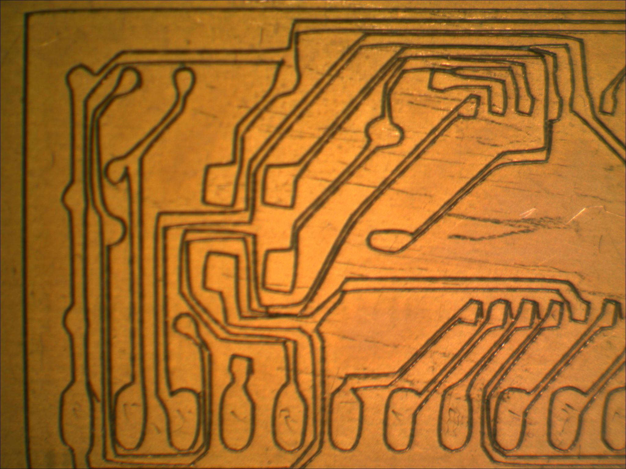
This takes about 2.5 minutes for my simple layout in the poster. It’s advisable to look at the cuts with a loupe or microscope and remove any copper “hairs” or obvious shorts or correct the problem areas. Use an ohmmeter to make sure all traces are good and there are no shorts.
6-16-2012 I have just uploaded a video of the paper cutter “cutting” a small single sided PCB – a PIC uP, few components and a header. Continuity of the result without removing any shards of copper showed 100% and one shorted line that was easily found under an eye loupe and fixed. For a movie of this cut, see below:
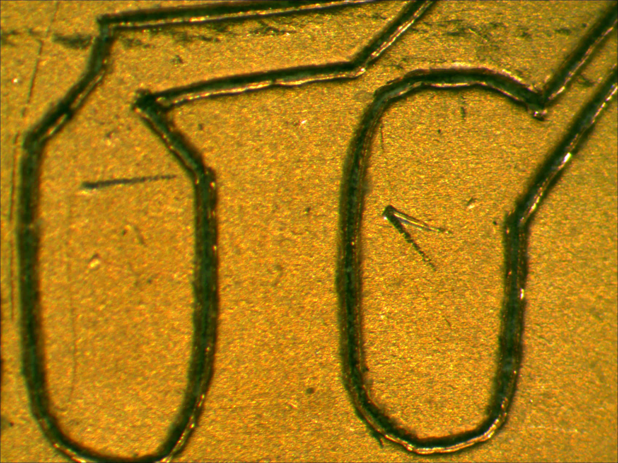
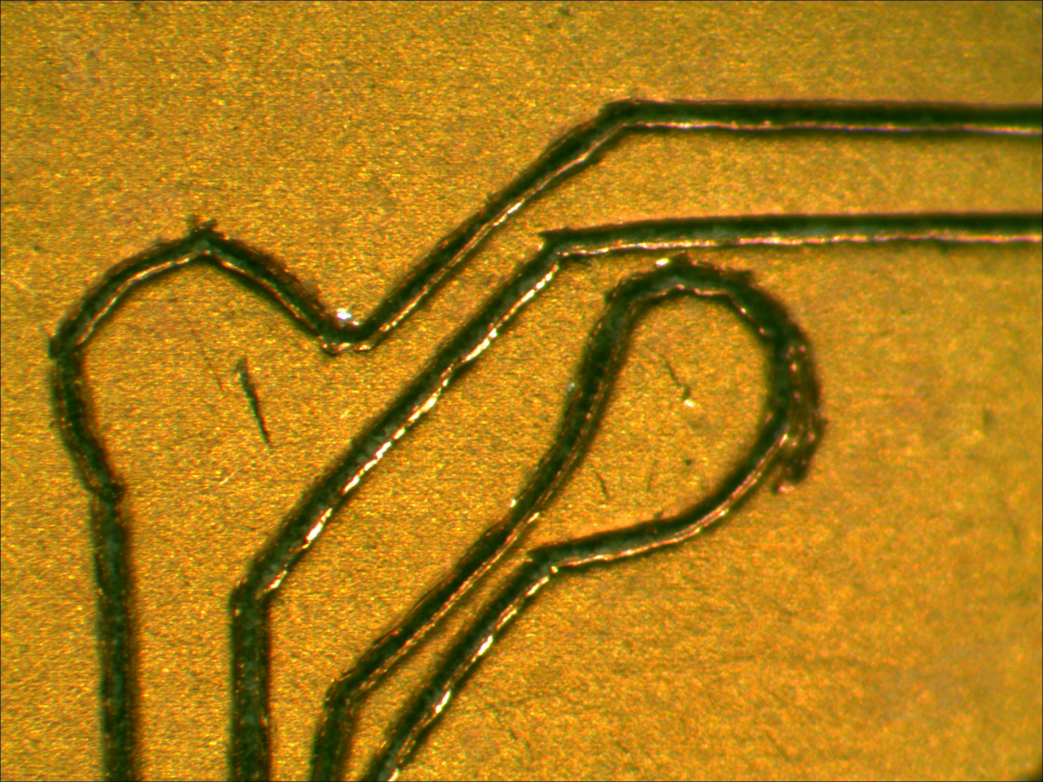
Wavy or non-straight lines will limit the minimum trace width. I believe this is a result of a combination of the trace function in the paper cutter software, incomplete cutter compensation or compliance in the cutting head (probably the latter).
6/22/2012 Last night I made this video – cutting’n’drilling.
I broke my “no mods or additions” promise for this technique and had to make a few small modifications –
– A holder for the flexible shaft rotary tool listed above. I bought an aluminum marker holder and used a lathe to make it fit the tool handpiece as shown in the video.
– I added a spring counter balance to the cutting head to help neutralize the additional weight of the handpiece, also shown in the video.
I had to figure a way to keep the cutter head down for a second or more and not move in X or Y while drilling. Solution – draw a 25 revolution square spiral in Silhouete Designer and scale down till you just reach X=Y= 0.000″. The cutter spends time trying to move the head through 25 “small dimension” squares but not moving (much) at all. I manually added these to where I wanted drilled holes. Now I need an automatic way to add these via the normal (Excellon) drill file outputted from EagleCAD with the normal Gerber 274x stuff. Drilling requires backing plate so you don’t drill through the cutter itself. I’ve been using a single thickness cardboard (like what’s on the back of a writing tablet). I adjust the flexible tool handpiece in the homeade holder and/or the position of the drill bit such that the tip of the bit just touches the bottom of the cutter when the cutter head is lowered to its mechanical stop , then I lock everything down. I taped the cardboard to the backside of the PCB board. Note the blue twist lock on the cutter holder will interfere with the capstan rollers so I will have to find a solution for that.
More to come…..
-
Contact
Mike (sinclair@microsoft.com)